Back in December 2019, I started playing with an Arduino kit. I discovered a cool 8x8 LED matrix and 74HC595 shift registers. Because I didn’t have the 8x8 LED matrix driver (like the MAX7219) so I decided to build my own driver using the 74HC595 shift register.
The repository is available at https://github.com/Its-Just-Nans/arduino-led-matrix
First version
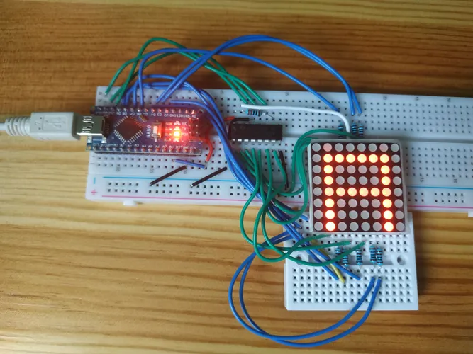
The first version was, as expected, a draft version with a classic breadboard and messy wires.
Of course, before this version I had to learn how to use the 74HC595 shift register, how to connect it to the arduino and play with it using basic buttons. I also learned how to connect the 8x8 LED matrix, to my own peril. It’s not just 8 connectors for rows and 8 connectors for columns, but it’s a bit more complicated than that.
RIP my first 8x8 LED matrix, burned out after misconnecting the wires 😔
The tricky part of working with an 8x8 LED matrix is understanding how it works. The matrix is made of 8 rows and 8 columns. To light up a LED, we have to make a circuit between a row and a column. The way it works means that we can only light up one row at a time. To display a frame, we need to light up each row one by one. For each row, we have to light up the LEDs that we want to display. Thanks to persistence of vision, we don’t see the flickering and we see the whole frame!

To program each row, we can use a single byte to store the data (because one row is 8 bits and it has only two values: 0 or 1). Another little interesting thing is that we can store the data little endian or big endian.
In that version, I programmed the arduino to display a simple animation on the 8x8 LED matrix (the alphabet letters). I also learned that I should turn off the LEDs before changing to a new row to avoid ghosting - we can see in the picture the ghosting effect on the first row.
Second version
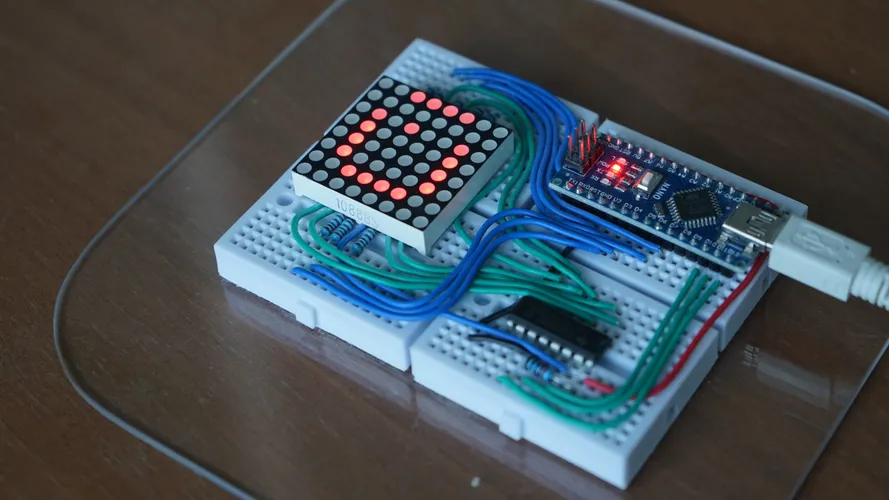
The second version is just a better arrangement of the first version. It uses four little breadboard glued onto a plexiglass sheet. The wires are now organized - using solid U shape wires.

Third version
The third version is made for practical use: if the matrix can only display the alphabet, it’s not really useful. Also, the arduino is memory limited, so even if I know which video I want to display, I can’t store it on the arduino. Here comes the computer! We can send the frames to the arduino using the serial port. The program is now serparated into two parts: the arduino part and the computer part. The computer part is a simple Python script that reads a video file and sends the frames to the arduino - it can also send basic string characters to display on the LED matrix. Again, we need to send the bytes rows is the correct format (little endian or big endian) to have a correct result.
Usage
Having a functional project is great, but can it run Bad Apple? 🤔
Yes!
More details about the video
The original video is 20min long so the video is speed up more that 5 times to match the bad apple video (the video is not frame-for-frame perfect because it desync at the end). Each frame is sent to the arduino using the serial port, and the arduino is displaying the frame on the 8x8 LED matrix.
Frames are generated from the original - resized to 8x8 - bad apple video. Fortunately, a similar project was done 3 years ago by aznguy.mp5 (available on https://www.youtube.com/watch?v=VGscIBfT7xE) with an open source code. All 12945 frames are available as a json https://github.com/aznguymp4/bad-apple-discord/blob/main/frames.json
On the video, we can see some flickering, it’s due to the frame rate of the video (60 fps). Thanks to our vision, we don’t see the flickering in real life. Sorry for the viewers!
The repository is available at https://github.com/Its-Just-Nans/arduino-led-matrix
